Software-Hardware Mapping in a Robot Design
pavol.jusko@gmail.com,
david.obdrzalek@mff.cuni.cz, petrusek@gmail.com
Abstract. In this paper[1] we present a way how to change the design of a
small robot for Eurobot contest from a design with a lot of hardcoded, hard to
maintain and hard to extend functionality to a more universal design with much
better maintainability and upgradability by use of software-hardware mapping.
In the process, we show how the change of communication topology and software design
rework helped to achieve the goal.
Keywords: autonomous robot design,
layered software design, software-hardware mapping
1 Introduction
Autonomous robot
design is a complex process covering many aspects and containing many
decisions. This paper describes second-year experience of MART (Mat-phys Robot
Team) – a student team based at Faculty of Mathematics
and Physics (authors of this paper are MART members) [1].
Our team in its current composition took part in Eurobot
autonomous robot contest [2] first in 2007. After this participation we
carefully re-evaluated our design in the light of our experiences and
observations gained during the work on our robot and during the contest itself.
In this paper, we present the way how we have changed
the design and implementation of our robot to be more robust, scalable and
simpler to maintain, upgrade and further develop. In our paper we focus on the
mapping between hardware and software and leave aside other tasks like
mechanical construction, high-level algorithms, overall robot “intelligence”
and others.
2 Original Design
Our robot was designed for Eurobot 2007 contest as the
first robot of a renewed team. It was build from scratch without reusing older
pieces of hardware or previously written software. The core controlling part
used standard PC based on mini-ITX motherboard with Linux operating system, and
all mechanical parts were constructed on purely amateur level.
The task we were facing was to design simple, yet robust
mechanism of message passing between sensors and effectors at physical layer and
their corresponding hardware abstraction layer in the software. Our old
hardware communicated using well known RS-232 interface, which is common on personal
computers and is easy to program in POSIX environment. The first implementation
connected all the peripherals to one microcontroller (MCU) which provided all
communications with the PC using its internal serial communication module. To
transfer the data, we developed a simple packet oriented protocol.
Since the number of peripherals increased, it became
necessary to add another controller. Therefore we had to split the RS-232 link to
multiple MCUs (using a simple hardware splitter), and start to use packet
addressing. The packets were created in the main control program. Upon reception,
the MCU firmware decomposed the packet, checked its consistency, took appropriate
action, and sent back an answer message, which contained complex sensor
information. Since the MCU response was obligatory and the format of such
message was fixed (= full information from the sensors), it can be seen that
the protocol complexity gradually raised to an unacceptable level and was no
longer simple.
Fig. 1. Original communication design before (left) and after (right) adding new peripherals
As we mentioned above, we wanted to develop universal
software for a universal robot which uses any kind of hardware. To achieve
this, we decided to implement a layered design. The layers should separate used
HW and higher logic of the robot. There were always doubts, how many layers do
we need to cover this abstraction and yet not to suffer from too complex design.
Too few layers would make the design messy; too many layers would make the
design unnecessarily complicated. With this on mind, we have created 3 layers named
”Communication layer“, ”HW abstraction layer“ and ”Smart layer”. From top to
bottom (see Fig. 2), the layer functions are:
- The
Communication layer handles the RS-232 link and takes care of the packet
representation. Its name depicts the functionality from the topmost layer point
of view and does not necessarily mean that actual communication with real
hardware modules must be performed from this layer (as will be seen in Chapter
4).
- The
HW abstraction layer performs two main middle layer tasks: it controls the
motors (and generally any actuator) and maintains localization data (and
generally any other environmental data). To fulfil these tasks, it is composed
of two objects, the Driver and the Localizer. The Driver object handles the
motors by setting their speed and braking. It provides the interface to steer
easily. The Localizer object reads the information from all devices which can
help robot positioning. It computes the exact location and let other objects to
read and exploit it.
- The Smart
layer contains, as the uppermost level, “The Brain” of our robot. The Brain is
the most important part of this layer so, we usually use this name for simplicity
to address the whole layer. The
Brain itself is implemented as a finite state machine. It tries to achieve all
the given objectives, drives the robot and takes care of all
the other things which can happen around the robot and are significant for its
work. This layer can also use any other peripherals connected by any other way
than using our RS-232-based link, for example the USB-connected web-camera or a
display.
Fig. 2. Original layered software design
The communication is the key of successful robot
behaviour. For example, the Driver needs some information about the real speed
of the wheels to correct the trajectory (e.g. when we want the robot to go
straight but due to any reason it diverts slightly), or the Brain reads the
position from the Localizer and gives orders to the Driver to achieve its high-level
goals (e.g. to navigate to a specific place).
This design fulfilled its goal to be easily adjustable
for other tasks. In 2007, we used the robot in two contests: Eurobot [2] and
Robotour [3]. They both focus on autonomous mobile robots, but they differ a
lot:
- Eurobot
is an indoor contest played on a relatively small playing field – a planar
table 2x3m, Robotour is an outdoor contest taking place in a huge park with
routes made of paver blocks and tarmac.
- Robots
in Eurobot contest must meet size limits (maximum height of 35 cm and
perimeter of 120 cm). These restrictions do not apply in Robotour, but in
this contest the robot can gain bonus point for the ability to carry a 5 kg
ballast load, whereas Eurobot robots are not permitted to carry any unnecessary
ballast at all.
-
During Eurobot contest, two robots compete on the playing field
in a 90 sec match and must avoid collisions with the opponent; in Robotour,
individual robots start for their 1km long journey in 5 minute intervals and
usually travel without any interaction with other robots.
- For
navigation during Eurobot contest, the robot can use beacons placed on fixed
position around the playing field, but there is no such equivalent in Robotour.
From the start, we designed our robot not to be limited
exactly to Eurobot contest. We wanted to create a more flexible platform and it
has proved that we have reached this goal. The necessary modifications needed
for the robot to be able to switch between Eurobot and Robotour consisted of
necessary changes to the traction and required almost no software modifications
except the highest level application logic due to different overall contest
setup.
In contrast with the fact the robot was successfully
used in the two mentioned contests, we have realized severe drawbacks in our
design of the hardware and the lowest software layer (Communication layer).
Firstly the hardcoded solution of packet handling is not maintainable, nor
expandable. For example, when we wanted to add a new peripherals (LED panel,
compass etc.), we had to make a lot of changes in the protocol handler (the
packet anatomy) and, worse, to make changes even in the hardware, namely to add
a new MCU. Further, the use of RS-232 implies certain bitrate, which could
cause unacceptably low data bandwidth (or latency) if higher number of devices is
connected or if more data transfers are needed.
In our case, we were not able to enjoy the qualities
of fast encoders because the maximum packet transfer rate would be exceeded.
This situation did not have a solution without complete protocol change, for which
we did not have time in the tight contest schedule.
The Eurobot contests rules are changing every year.
Also, different contests have different rules and so need different robot
implementations. To prepare the robot for a new contest edition or another
contest at all, it is obvious the mechanical part of the robot need a change.
We also wanted to develop and add new devices to improve the cognition and
mobility of the robot and therefore changes in software were necessary too. We
used this as an opportunity to improve the software design as well, and the
next edition of Eurobot contest was the right impulse to start.
3 Hardware Changes
In order to address the disadvantages we
removed the one-to-one concept and implemented new communication based on bus topology.
The layered design allowed us to change quite a lot of hardware-related parts
with only small changes to the software. We have chosen the well known I2C
high speed bus [4] with SMBus-based packet protocol [5] as the new transport
link. This allowed us to use full I2C high speed transfers while
gaining from the SMBus protocol comfort. Our devices are connected to the
computer using 3rd party USB to I2C bridge [6]. In Linux, the preprogrammed
kernel I2C support allows its easy use (e.g. it
handles packet transfers and performs the SMBus checksumming). On the application
level, the I2C-connected devices are represented by regular files with
regular read/write operations on those files. On the system level, the read/write
I2C transfers are implemented using a set of callbacks which convert
the binary application data to the SMBus protocol compliant packets and vice
versa.
Fig. 3. New communication design
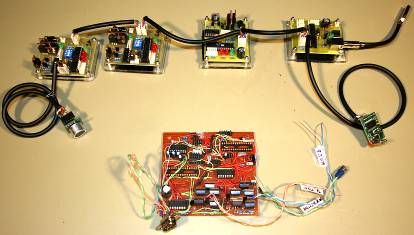
Fig. 4. Comparison of peripheral modules: new I2C version (top), old RS-232 version (bottom)
The individual modules for motor control were implemented as a “HBmotor board” (see Fig. 5 or reference [1]). The board consists of one MCU controlling the board main functions (Atmel AVR-based microcontroller, in our case), H-Bridge for motor power drive (standard MOSFET circuit driven by PWM - Pulse Width modulation) and interface for encoders and switches (digital inputs). The MCU firmware implements following tasks:
- control of the H-Bridge operation: enable/disable rotation, direction and PWM signaling for motor rotation control
- motor feedback: input from encoders giving odometry information for the control software
- SMBus slave function for communication between the main control PC and this module.
Even the HBmotor board was designed for motor control, its MCU firmware is reusable for other sensor and effectors boards, for which purpose the hardware specific code must be changed but the core can remain unchanged.
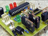
Fig. 5. HBmotor board schematic diagram and photo of implemented board
4 Software Changes
Due to the new hardware design, the modules changed to
be independently communicating with the PC. It allowed us to use this behaviour
also in the object-oriented software design. The old packet handler called ”Bios“
in the Communication layer became unnecessary and was replaced by independent
objects which represent real devices. These objects create a mapping between
the software and the hardware. Consequently, more classes appeared at the HW abstraction
layer. Their purpose is to provide more information for the Brain and also for
other objects in the same layer to increase their power. The diagram (see Fig.
6) may now look bigger, but the design consists of bigger number of smaller
independent modules whose size does not reflect code size (in fact, the total size
of the code remained roughly the same).
To separate the physical layer implementation (in our
case SMBus communication) from the upper level software, we have created Linux kernel
modules for handling the devices. These modules use standard Linux virtual
filesystem (sysfs) I2C implementation, which is based on directories
and files: each directory represents one device and a file in a directory represents
certain ability of the respective device. Our simple approach binds each file to
one MCU SMBus register. This design decision separates the hardware
implementation (MCU code, choosen bus technology etc.) from the application which
uses this hardware. Besides other advantages, such approach easily allows
different people to work on these separate parts (which was also the case of
our team).
Every device is now handled by an object used for the
communication (via read/write operation upon I2C interface files).
The objects provide the interface to access all needed low-level device data
from other objects. On the HW abstraction layer, new classes may be implemented
to raise the functionality of the raw devices so that they can be considered
“smarter” by the Brain or other objects in the HW abstraction layer. For
example, such class could implement moving-average or a sample memory for a range-finder
device which standardly provides only a single value representing the range
finder actual measurement. Also, with the use of object-oriented programming methods
it is now easy to use more devices of the same kind or of the same type origin
as their software abstraction will be created using simple instantiation and inheritance.
After changing the communication to asynchronous
model, straightforward implementation could easily lead to every single device
being handled by a separate thread. However, for certain cases this is not the
right way. For example, the encoder information from the two driving motors
should be read synchronously to eliminate readout differences and jitter. Using
independent threads, the load on the I2C bus could also cause unwanted
harmful peaks because of the unpredictable process scheduling performed by the operating
system. To better benefit from the asynchronous communication, we decided to
implement a very simple scheduler instead of a completely new threading model.
This scheduler helped us to shorten the waiting period between individual
cycles of communication with a specific devices (e.g. motors with encoders, in
our case via the HBmotor board). This decision lead to improved reaction time
of the Driver and the information topicality in the Localizer (see Chapter 2).
As the communication is one of the most important issues to solve to reach the overall goals, we gave special attention to its design and implementation. At the same time with the completeness, we also aimed for simplicity. In our design, the layers communicate strictly with only adjacent layers in a standard way. From top to bottom, the process is following (see also Fig. 6):
- The Brain is implemented as a finite state machine. It uses information from the HW abstraction layer to accomplish its top-level objectives – it reads the robot’s position by calling the Localizer (getPosition()) and guides the robot by giving orders to the Driver (gotoXY(position)).
- The orders are propagated from the HW abstraction layer to the Communication layer by setting the right speed for each individual motor. The Driver receives the information about desired direction and the speed from the Brain and regulates the individual motors on each powered wheel using standard PID (proportional–integral–derivative) regulation. The PID regulation needs data from the motor encoders, which is provided by the Communication layer objects via the Localizer.
Fig. 6. New layered software design
- Information needed by the Brain for navigation is provided by the Localizer and Range finder objects from the HW abstraction layer. These two objects encapsulate the individual modules information and thus the robot may be easily supplemented by new hardware providing nearly any other type of data. In such a case, the data for the Brain would be processed by the Localizer first and so can be of the same format as before.
- Basic task for the objects in the Communication layer is to provide interface between the HW abstraction layer and the operating system Kernel modules (files). Here, the Scheduler takes care of balanced communication.
- To reduce the unnecessary communication and to improve the reaction speed, we decided to implement certain simpler functionality in the (rather low positioned) Communication layer. This functionality can be depicted as a parallel to reflexes, which do not have to be controlled from the high level control modules. For example, without the need to process inputs and give orders by the Brain, the motors are able to work in a simple self-control mode. When the Brain switches the motor to this “goUntilBumper” mode, the motor (or precisely the instance of the motor object) takes care of the necessary action: using the set speed, the real motor is driven until its bumper (every HBmotor board is equipped with a bumper input) signalizes its activation. Then, the motor is automatically stopped and the information is propagated to upper layers. Such event can be used by the Brain for qualified decision about further robot activity. This approach seems to have a lot of benefits, because it is easily usable by higher layers and at the same time upper layer does not have to deal with it. Furthermore, such automatic reaction is immediate and is not burdened with communication between layers.
5 The Results
With the new design, the maintainability and
upgradability of our robot improved a lot. To add any new device now we need only
to:
1. Attach
it to the I2C bus and assure it can communicate using SMBus protocol.
2. Provide
the kernel module a function responsible for translation between SMBus-transferred
data and their corresponding virtual data files for this device.
3. Create
a communication and logic class, which knows how to interpret the transferred
data. This class may either provide the data “as is” or may perform quite
complex data processing to simulate the device capabilities and thus increase its
usability.
4. Use
the new module from the Smart layer of the software or from other device objects.
For the three first steps, we have prepared (and
successfully used during work on our robot) basic prototype code which may be
easily adapted with specific new device attributes:
1. A
MCU firmware prototype, which provides the SMBus functionality and leaves space
for specific device handling .
2. A
stub kernel module, which transfers data written to the virtual file onto the I2C
bus and data received from the I2C bus from its dedicated device into
the virtual file buffer.
3. A simple
class, which encapsulates the file data and allows standard read / write
operations. This class may be arbitrarily extended to provide more complex functionality
as mentioned earlier.
(4. The fourth step is using the data in the highest
layer which obviously cannot have a prototype implementation.)
During the depicted process, a lot of hardcoded stuff
has been removed and replaced by new code which follows the proposed methods
and design decisions. This code is simpler and easier to read and the new
design allows improving the robot by adding new devices with only minimal effort
needed.
It is now possible to add a wide variety of new devices,
e.g. the infrared range-finder, acceleration meter, GPS receiver as new
sensors, or new motors, tool handlers or other various actuators and manipulators.
Even the change of the transport link from I2C with SMBus to other
standard transport (e.g. CANopen) is easily possible. We plan to add such
peripherals to our robot so that it can be used for new contest editions and
even for other contests at all. Thanks to the new design, any such single
change will not affect other parts of the robot or the software.
6 Conclusion
In our paper, we have shown a new design of a
robot as a result of a change from a design with a lot of hardcoded, hard to
maintain and hard to extend functionality to a more universal design with much
better maintainability and upgradability. The new design has proven its
qualities; it provides the functionality of the old design and at the same time
it gives much better opportunities for the future.
Acknowledgements
The work was partly supported by the project
1ET100300419 of the Information Society Program of the National Research
Program of the
References
1. Homepage
of MART team: http://mart.matfyz.cz
2. Eurobot
Autonomous robot contest: http://www.eurobot.org
3. Robotour
competition: http://robotika.cz/competitions/en
4. I²C-bus
specification: http://www.nxp.com/i2c
5. System
Management Bus (SMBus) Specification: http://smbus.org
6. i2c-tiny-usb: http://www.harbaum.org/till/i2c_tiny_usb/index.shtml